
Monodraw: Progress Update #1
It is finally time for our first Monodraw beta progress update. It has taken a bit longer than I expected but we have made some significant progress and more importantly, completed some essential improvements to how the app works.
Before we go any further, I want to set out what you can expect from us when it comes to Monodraw's development. My mission is to be completely open about what's happening behind the scenes, what work is being done and what our plans are. It is my intention to provide regular updates on our blog so that you are not left in the dark, wondering what is happening – if you don't see any updates for a while, it probably means we are busy working and there is nothing that we can announce just yet. Always feel free to send me an email or just tweet @milend.
The one thing I can promise you is the truth – no corporate or marketing speak. Our customers deserve to be treated with respect and honesty.
Overview
Next up, I want to explain why it has taken longer than expected to provide the first status update. The aim of the beta program is to release a build of the app that is not quite fully featured or polished but provides a solid foundation to build on. After the Monodraw reveal, we want back to drawing board and noticed two important shortcomings:
- The position of shapes could not be dynamically specified, apart from line end points. This makes it harder to express the relationship between shapes, so you end up having to manually move and re-adjust them.
- Shapes are not fully editable. For example, you could only edit the corners of a rectangle and if you wanted to change a single character, you had to create a separate surface shape, position it above and set a character there.
I came to the realisation that the tool was fighting you rather than helping you – exactly the opposite of what was expected. Tools should be empowering and allow you to easily create rather than forcing you to express yourself in their "language" (i.e., the abstractions they provide).
This meant I had to make two major changes to the fundamental way Monodraw worked – introduce dynamic positioning and fully editable shapes. As the changes affected the foundations of Monodraw, I had to refactor the affected parts so that everything is nicely designed and fits together correctly. While refactoring does take longer, the sooner architectural changes are made the better – you end up with a better maintainable codebase (so easier to improve in the future) and the code should have less bugs. It's a win-win for both developers and users.
Dynamic Positioning
Dynamic positioning is a very powerful concept that can be used to express the spatial relationship between shapes, so that when you move a single shape, all related shapes would automatically move with it. You might be familiar with the concept of anchor points where you can have lines that are attached to other shapes. We have taken the idea further and every shape's position is completely dynamic and attachable to any anchor point – you can create arbitrarily long chains.
Let's take a look at how it works for any rectangular shape (rectangle, text field and surface). The position of such shapes is defined by three properties: a dynamic point (which can be attached to any anchor point), a size and a corner position (e.g., top-left). For example, you can express the following relationship: the top-right corner of a rectangle of size 10 by 5 is attached to the start point of a particular line. There are no limits of the complexity of those relationships, they can span multiple shapes, e.g., you can attach a shape to another shape which in turn is attached to yet another one.

Custom Anchor Points
While dynamic positioning provides you with a lot of power to express the spatial relationship between shapes, it is limited by what anchor points you can attach to. For a rectangle, we provide 17 predefined anchor points. For lines, the start point, end point and any midpoints are all anchors, in addition to special points that lie on the segments themselves (orthogonal segments get 3 anchor points while step segments get one).
But any predefined anchor points will never be enough to handle every case out there. That's why I have added support for custom anchor points and you can position them anywhere you want. Making a circuit diagram with an arbitrary number of inputs and outputs becomes a breeze.

Line Labels
When creating diagrams, lines commonly have labels to clarify their meaning, so it is important for Monodraw to be able to cater for that use case. When it comes to the labels themselves, the question of layout arises immediately – how does the line decide where the label would appear? What line sweep would be used? What if the user wants fine-grained control? The common answer to these questions has usually been: the label decides and if the user is unhappy, they can create a separate label and position it manually. Obviously, every time the line is moved, the user would have to re-adjust the label's position again.
Monodraw's philosophy is that the user should be in full control. So how does one create a line label? Remember that each line provides anchor points along the segments and that text fields are dynamically positioned. When you put the two together, a line label is just a text field attached to one of those anchor points! One of the major benefits of this approach is that because the label is just a normal text field, you get full control over how the text is laid out - line sweep, text position, alignment, everything. Furthermore, any shape can become a line segment label – it just needs to be attached to the segment anchor point.
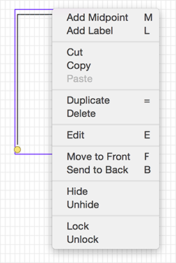
As making labels is a very common operation, it can be easily accessed via a contextual menu.

Fully Editable Shapes
Every time we used Monodraw, we were continually annoyed by the inability to be able to directly edit the characters of all the shapes. While the surface shape gives you an empty canvas, lines, rects and text fields were not fully editable which lead to a lot of frustration and having to use tedious workarounds.
No more of that – all shapes are now fully editable. The app also tries to express any changes you make in a way that preserves their meaning. For example, if you edit the border of a rectangle and if you resize it, those changes will be expressed as "set character X along the bottom border".
In addition, each shape supports "smart points" which are now highlighted in red during editing. The corners of a rectangle and the endpoints of a line are such points – when edited, they will be stored in a special way and will preserve their characters during any changes to the shapes themselves.

Smaller Improvements
I have also made some smaller improvements along the way, namely:
- You can paste text from the clipboard directly into the app (a surface shape will be created containing the text).
- Shortcut keys have been added to the contextual menus. Keyboard navigability of the app is extremely important to me, so there will be more efforts in that direction throughout the development cycle.
- When initiating shape editing with a double-click, the initial selection will now correctly be set from the mouse cursor (previously, it was always the top-left corner).
The Road Ahead
While we are getting closer to the beta, there are still quite a few bits of work left. We have already decided to cut back on some of the features that would have been included, so that you can get your hands on the app sooner – I will provide further details in due course. The next area of focus would be the inspector / assistant. It would mainly involve interface adjustments but also changes which would provide better customisation of the existing shapes. As usual, we will provide an update on our blog, so make sure to subscribe in your favourite RSS reader or just follow @Monodraw.
Have you already reserved your place in the beta program? If not, do it now!
 You should follow @Monodraw for the latest updates.